


A-Series Premium Powered Wheelchair
Product Overview & Technical Catalogue
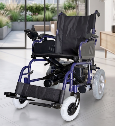
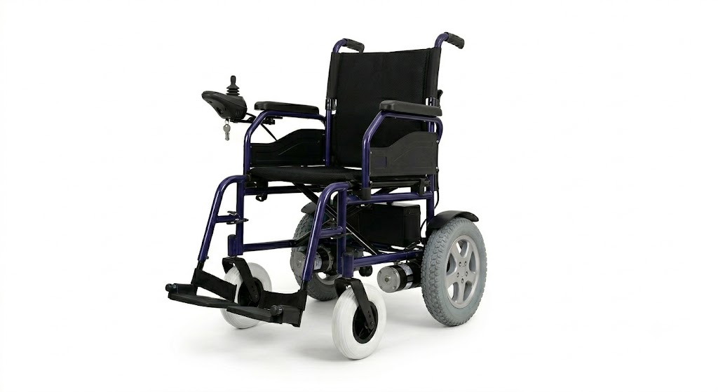
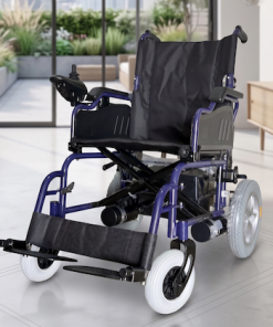
The A-Series Powered Wheelchair is a medical-grade, high-performance mobility solution engineered to provide exceptional autonomy, safety, and comfort. Featuring dual-motor rear-wheel drive, intelligent fluid joystick controls, and a lightweight optimized folding geometry, it shifts seamlessly from an agile indoor navigator to a highly portable travel vehicle.
I. Technical Specifications
| Specification Parameter | Value / Dimension |
| Outer Dimensions (L × W × H) | 1060mm × 630mm × 910mm |
| Folding Dimensions (L × W × H) | 760mm × 350mm × 730mm |
| Net Weight (Including Batteries) | 57 kg |
| Maximum Weight Capacity | 100 kg |
| Castor Diameter (Front Wheels) | 200mm (Approx. 8 inches) |
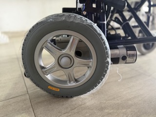
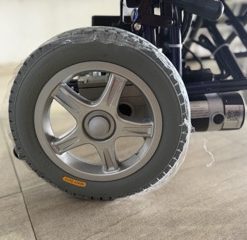
| Driving Wheel Diameter (Rear Wheels) | 330mm (Approx. 12.5 inches) |
| Seat Dimensions (Width × Depth) | 410mm (W) × 400mm (L) |
| Operational Speed Range | 1 – 6 km/h |
| Maximum Climbing Angle (Creeping Capacity) | 12° |
| Obstacle Clearance Capability | 50mm |
| Minimum Turning / Stopping Distance | 1 meter |
| Running Range (Per Full Charge) | Up to 20 km |
| System Operational Noise Level | ≤ 65 dBA |
| Battery Configuration | 2 × 12V = 24V, 28Ah Lead-Acid / Gel |
| Motor Configuration | 200W × 2 (Dual High-Torque Rear Drive) |
| System Charging Parameters | 5A Output / AC 220V Input |
Standard Package Includes: > 1 × Main Powered Wheelchair Structure, 1 × Dedicated Smart Charger (5A), 2 × Integrated Battery Packs, 1 × Premium Comfort Seat Cushion, and 1 × Ergonomic Back Cushion.
II. Setup, Installation & Calibration Guide
1. Frame Unfolding & Chassis Assembly
-
To Unfold: Push downward firmly on both outer edges of the seat upholstery until the main frame locks into its secure, rigid tracking configuration.
-
To Fold / Collapse: Pull upward directly on the middle center-line of the canvas seat upholstery. The battery box and controller can remain intact or be uncoupled for tighter spaces.
-
Leg Rests: Install the adjustable leg rests into the front receiver brackets, lock them at the desired orientation, and insert the integrated safety anti-tip pins.
2. Battery Box & Wiring Matrix
When servicing cells or replacing the power bank, adhere strictly to terminal serialization to prevent system over-voltage:
-
Series Jumper: Link the positive terminal (anode) of Battery A cleanly to the negative terminal (cathode) of Battery B using the thick secondary bridge wire.
-
Main Positive Line: Secure the main Red Cable directly to the remaining open positive (anode) terminal of Battery A.
-
Main Negative Line: Secure the main Blue/Black Cable cleanly to the remaining open negative (cathode) terminal of Battery B.
-
Chassis Connection: Slide the battery boxes into the support bracket rails, hook the housings to the primary support pole, and align the heavy-duty power coupling plug directly into the receiver socket underneath the chassis.
3. Controller Configuration
-
Mount the controller unit securely onto the structural armrest bracket and tighten the lower retention adjustment knob.
-
Route the wiring loom safely beneath the armrest to avoid pinching.
-
Plug the drive system connectors into their corresponding labeled ports under the chair: the cable marked LEFT connects to the left motor drive loop, and the cable marked RIGHT connects to the right motor drive loop.
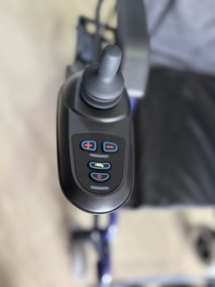
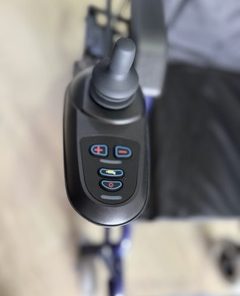
III. Intelligent Controller Operations
-
Power On/Off: Press the physical power button. The indicator display light array will illuminate immediately, showcasing current battery capacity (Green = Full, Amber = Medium, Red = Critically Low / Charge Immediately).
-
Speed Modulation: Use the Speed Up and Speed Down keys to shift acceleration thresholds between settings 1 through 5 depending on room layouts or terrain.
-
Directional Joystick: Pushing the joystick forward, backward, or sideways dictates steering orientation. Releasing the stick to its absolute center neutral position engages the automatic electronic regenerative braking loop instantly.
-
Free-Wheel (Manual Push) Mode: If battery reserves drain out, an assistant can manually push the wheelchair by releasing the two manual clutch engagement levers directly mounted on the rear motor gearboxes.
-
Warning: Never disengage the clutch levers on an incline or slope.
-
🔒 System Lock & Unlock Alarms
To protect the vehicle against unauthorized usage, a computer lock profile can be toggled:
-
To Lock: While the controller power is ON, press and hold the Power Button continuously for 4 seconds. The display screen will turn off immediately, all status LEDs will flash once, and the onboard horn will emit two quick sound profiles. The chair is now locked.
-
To Unlock: Press the Power Button once. The battery gauge LEDs will begin executing a slow, continuous right-to-left chase sequence. Within 10 seconds of this sequence beginning, press the physical Horn Button twice. The display will revert to normal operation, confirming system authentication.
IV. Self-Help Diagnostics & Troubleshooting Matrix
The integrated primary controller monitors system electronics in real time. If a fault condition is detected, the red service indicator LED will blink continuously. Count the number of consecutive flashes between pauses to diagnose the state:
| Flash Code | System Diagnosis State | Recommended Corrective Action |
| 1 | User / Configuration Fault | Possible system stall timeout or accidental joystick hold at startup. Power the unit off, release the joystick, and cycle power back on. |
| 2 | Battery Bank Fault | Core voltage drops below the standard operational minimum. Connect the 5A charger immediately. If fault persists, check cell terminals for oxidation. |
| 3 | Left Motor Disconnect | Left drive loop broken. Inspect the Left motor quick-release line plug, connection pins, and structural wiring harness paths. |
| 4 | Right Motor Disconnect | Right drive loop broken. Inspect the Right motor line plug interface and ensure pins are pushed securely into place. |
| 5 | Left Parking Brake Error | Left manual clutch lever is uncoupled or the electric brake loop registers open circuit resistance. Lock clutch engagement lever. |
| 6 | Right Parking Brake Error | Right manual clutch lever is uncoupled or internal parking brake loop is broken. Lock the right gearbox engagement clutch. |
| 7 | Joystick Offset Discrepancy | The controller lever was deflected away from absolute neutral center during the boot sequence. Power off, ensure joystick is clear, and restart. |
| 8 | Main PCB Controller Fault | Internal logic processor board registers a structural processing error. Consult an authorized service technician. |
| 9 | Bus Communications Loss | Signal communication broken between the upper joystick command pad and the lower motor driver board. Inspect the serial data cable lines. |
| 10 | System Over-Voltage Threshold | Input voltage parameter exceeds maximum allowance. Check connection serialization balancing for terminal crossing errors. |
⚠️ Critical Maintenance Safeguard: Always maintain the inflation pressure of pneumatic rear wheels and front castors strictly within 3 kgf/cm² – 4 kgf/cm². Low tyre pressure significantly drops maximum running range metrics, compromises tracking accuracy, and decreases automatic braking stability. Safely clean the structural frame and upholstery frequently using mild, non-abrasive detergents.
Be the first to review “A SERIES ELECTRIC WHEELCHAIR”
Related products


WHEELCHAIRS


WHEELCHAIRS


WHEELCHAIRS

WHEELCHAIRS

WHEELCHAIRS


WHEELCHAIRS

Uncategorized
Reviews
There are no reviews yet.